The PSP scene survives on small mods like the Baryon Sweeper. Done right, a Baryon Sweeper-equipped battery puts the console into service mode at boot — opening the door to firmware repairs and modding without a Pandora’s Battery you may not have anymore. This is the build I followed end to end, with each step pinned to the photo I took at that moment.
If you’d rather skip the writeup and follow the photo tutorial, it’s also live at /baryonsweeper.
Why bother
Pandora’s Batteries are increasingly rare and the official ones don’t always cooperate with non-Sony cells. A Baryon Sweeper-equipped battery does the same job using a $3 USB-to-serial module instead of a sacrificial cell. It’s reusable, you can take it apart, and once it’s done you have a tool you’ll keep for as long as you keep your PSP.
What you need
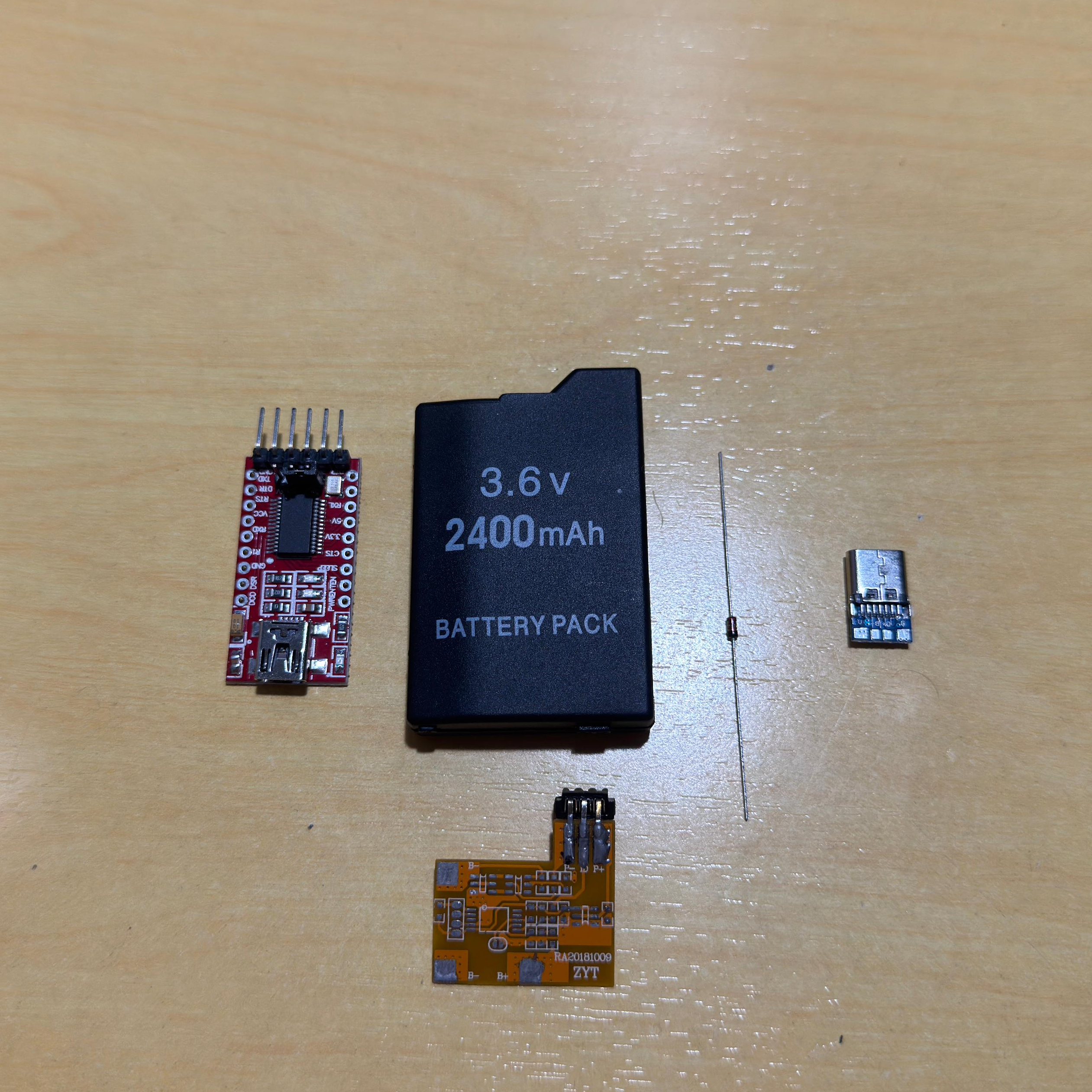
- FT232RL — USB-to-serial controller module. The brain of the build.
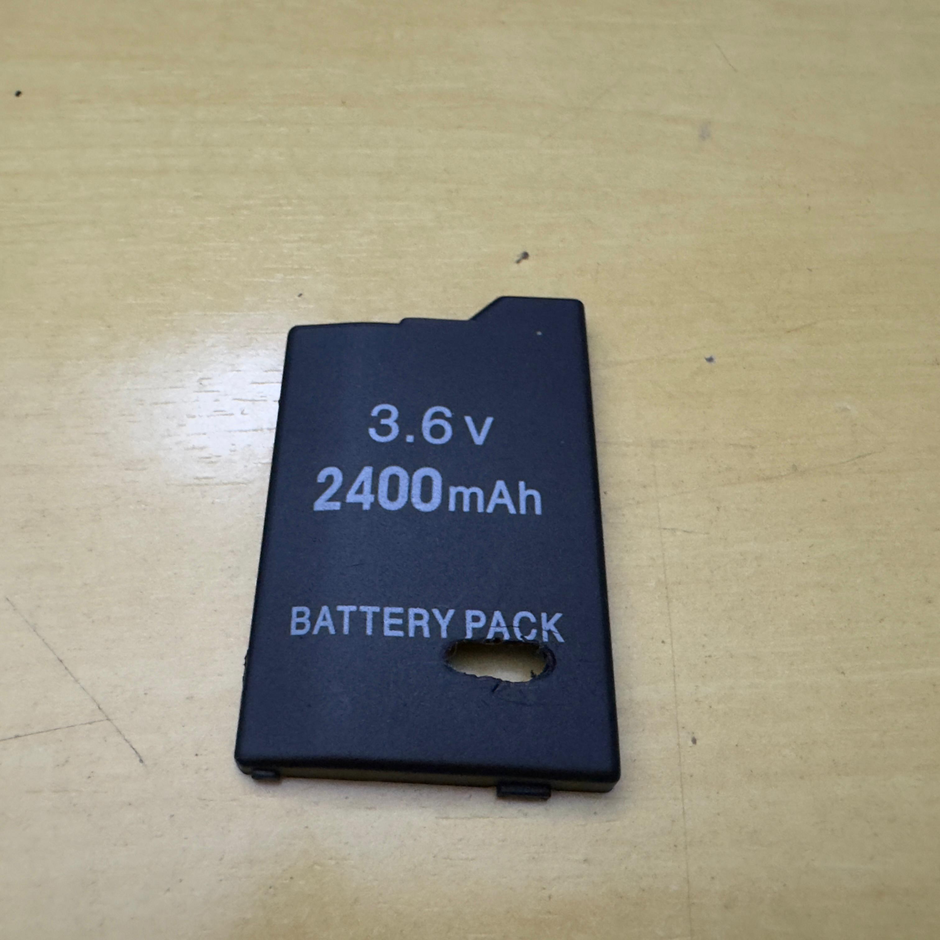
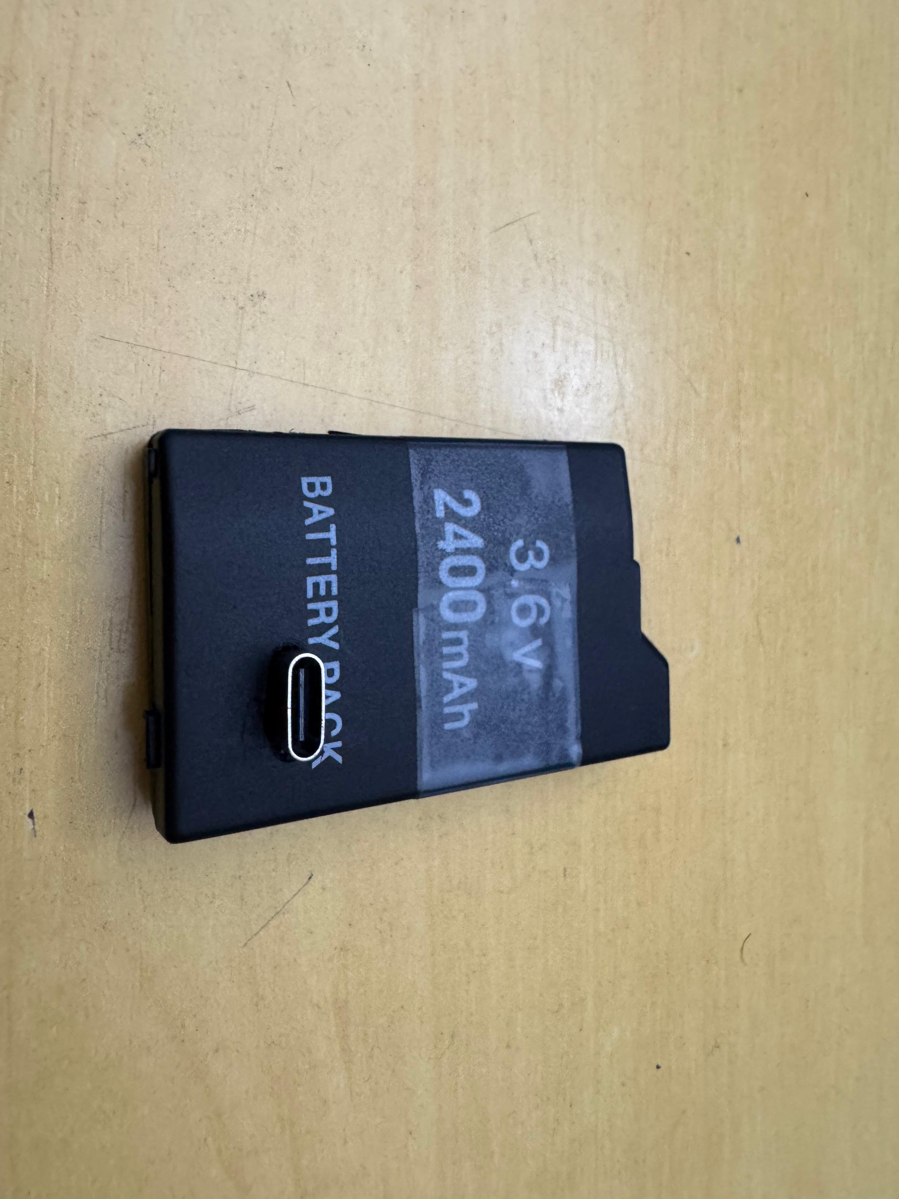
- PSP battery donor — preferably a third-party one. You’ll be ripping it apart, so don’t sacrifice a working OEM unit.
- 1N4148 diode — for the signal line.
- Wires — different colours save you a lot of pain later when tracing things.
- USB-C breakout — replaces the original charging connector.
- Soldering iron with a fine tip, electrical tape, hobby knife — and patience.
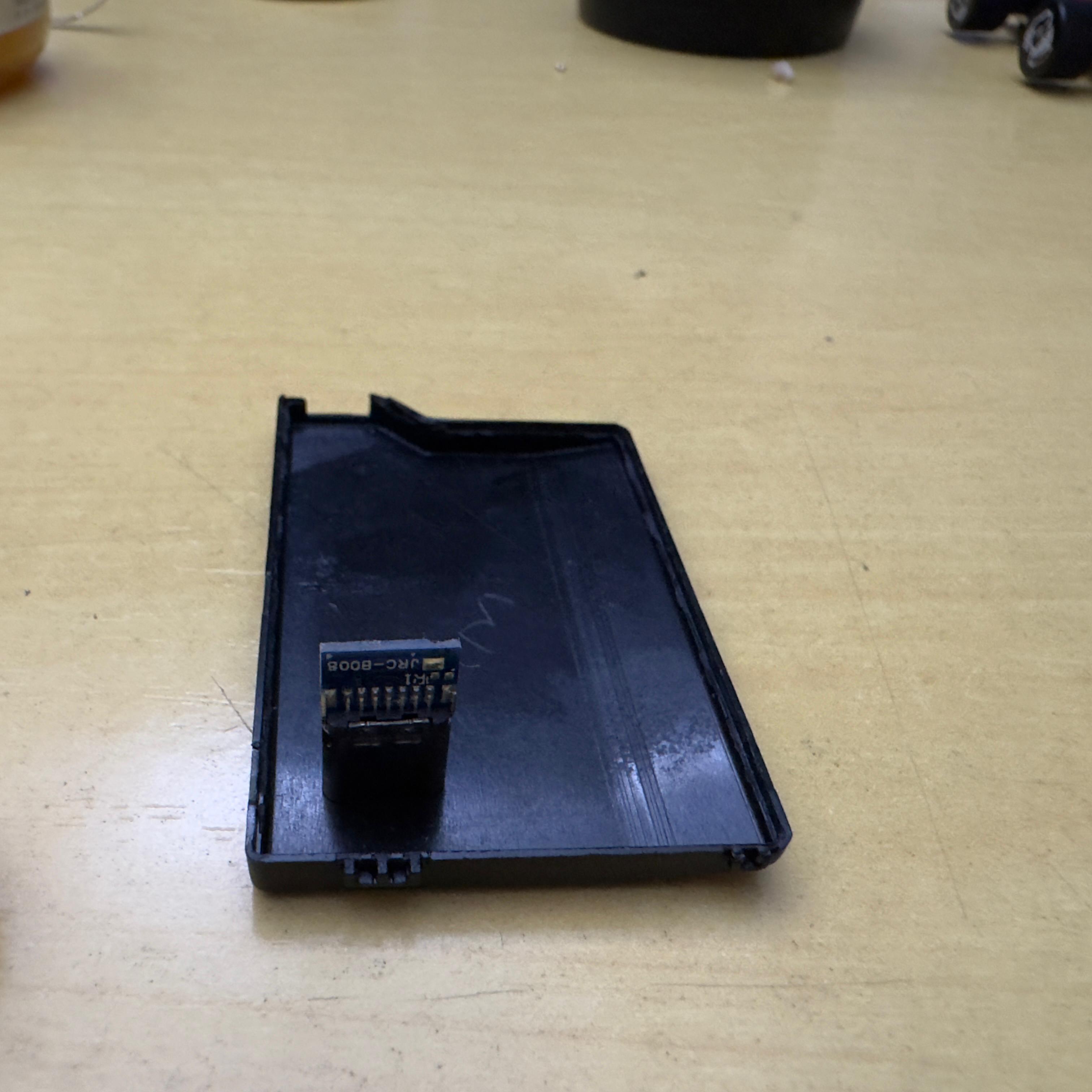
Crack the donor battery
Pop the case open, lift the cell out (we don’t need it), and free the protection PCB. Everything goes except the connector that mates with the PSP. Then scrape the data, voltage, and ground traces until copper is exposed.
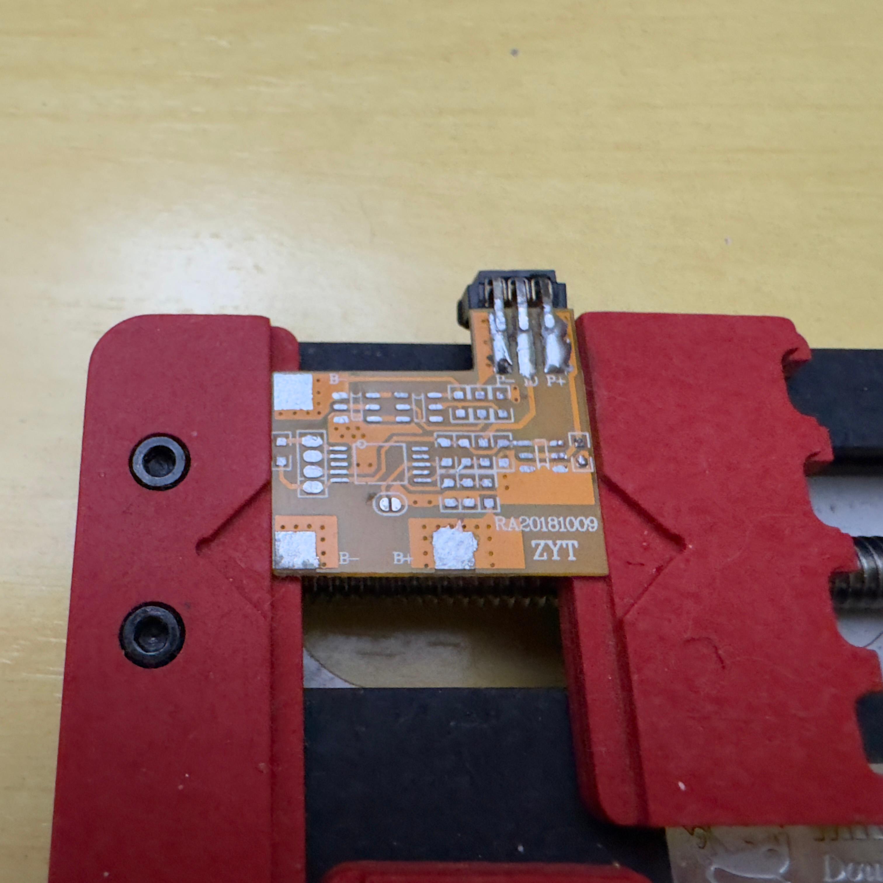
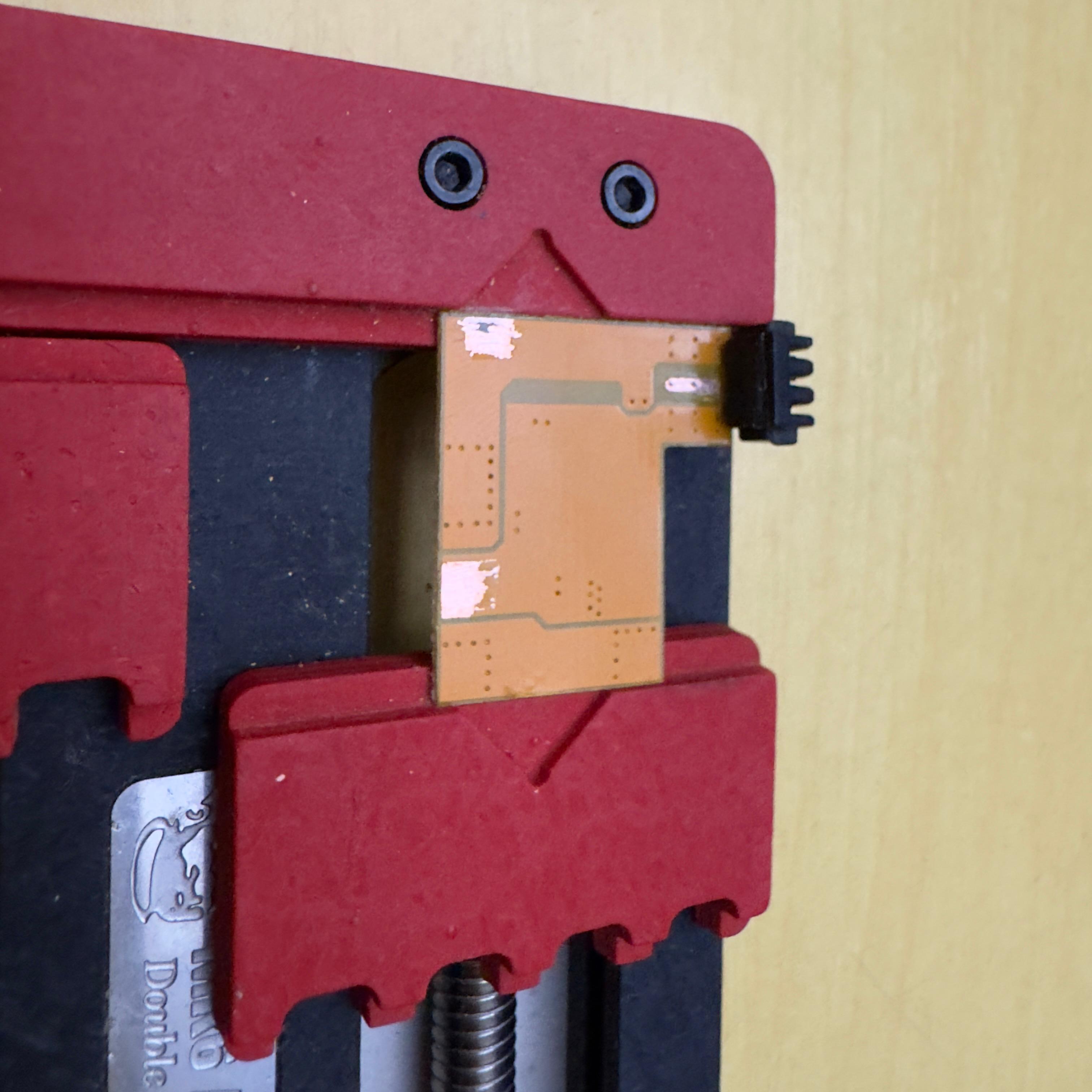
Flip it over and double-check the back: the through-hole pads you’ll solder onto need to be clean here too.
The scraping step is where most beginners give up. Take it slow with a hobby knife and check with a multimeter that you actually exposed metal, not just lifted lacquer.
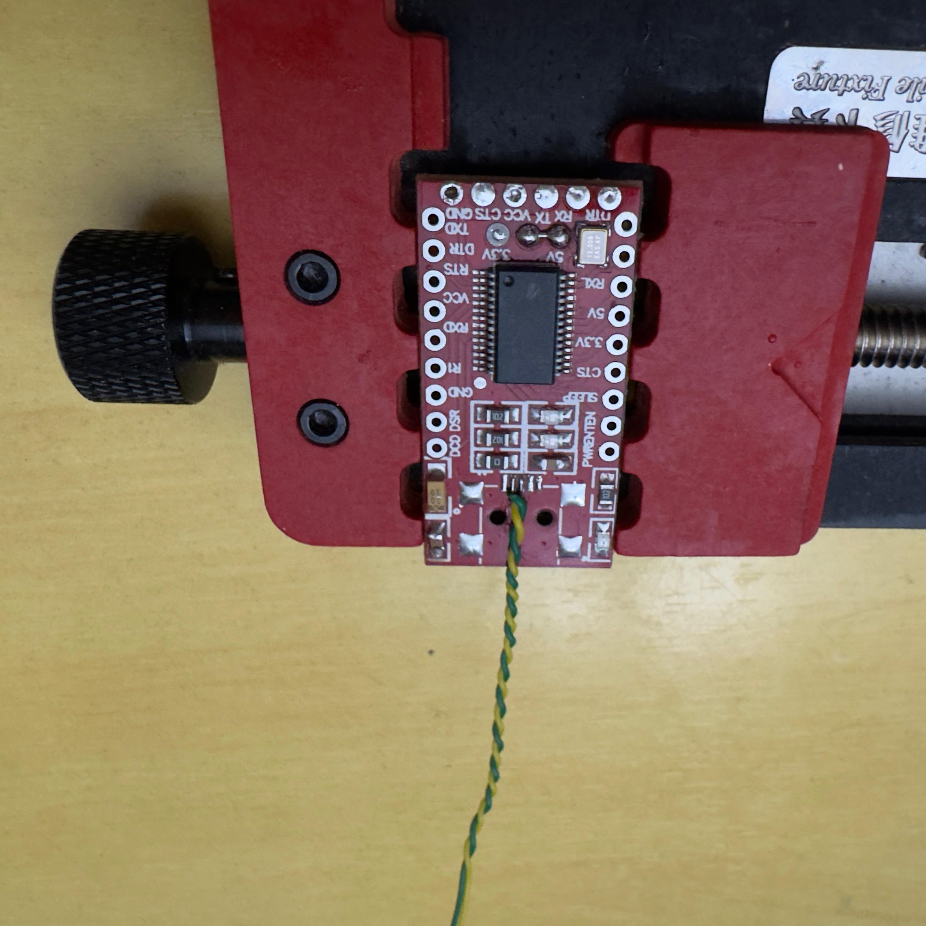
Prepare the FT232RL
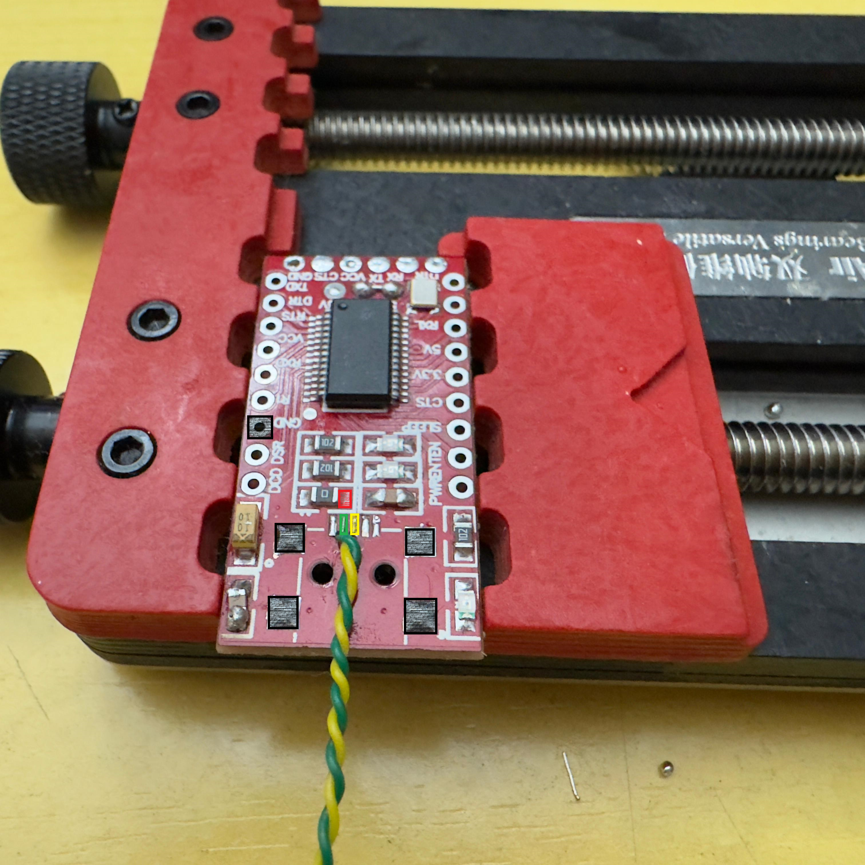
Bridge the 5V solder jumper on the back of the module so it sources 5V continuously instead of waiting for USB enumeration. Strictly speaking, that’s the only modification the FT232RL needs.
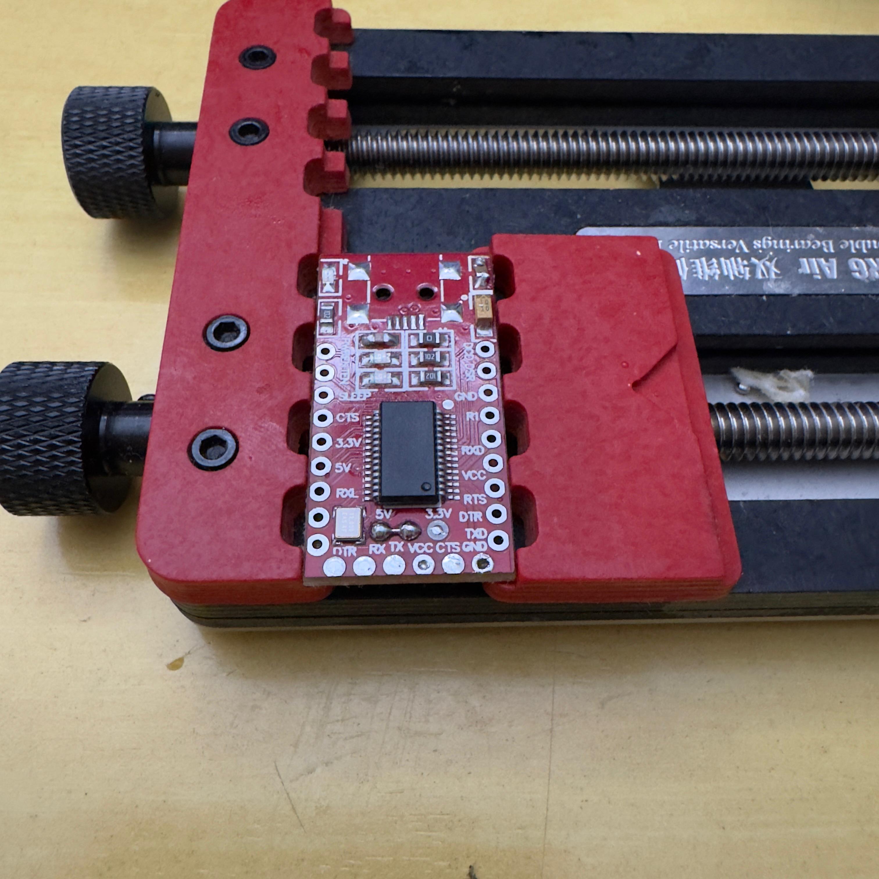
If you only ever see it from the top (like in the photo above), pop it off the holder and check the back — the jumper is a tiny solder bridge between two pads near the regulator.
Solder the 1N4148 onto the battery PCB
Bend one leg of the 1N4148 into an L and solder the cathode (the side with the band) onto the data pad of the PSP connector. The free leg sticks out — that’s where the FT232RL’s TX wire will land later.
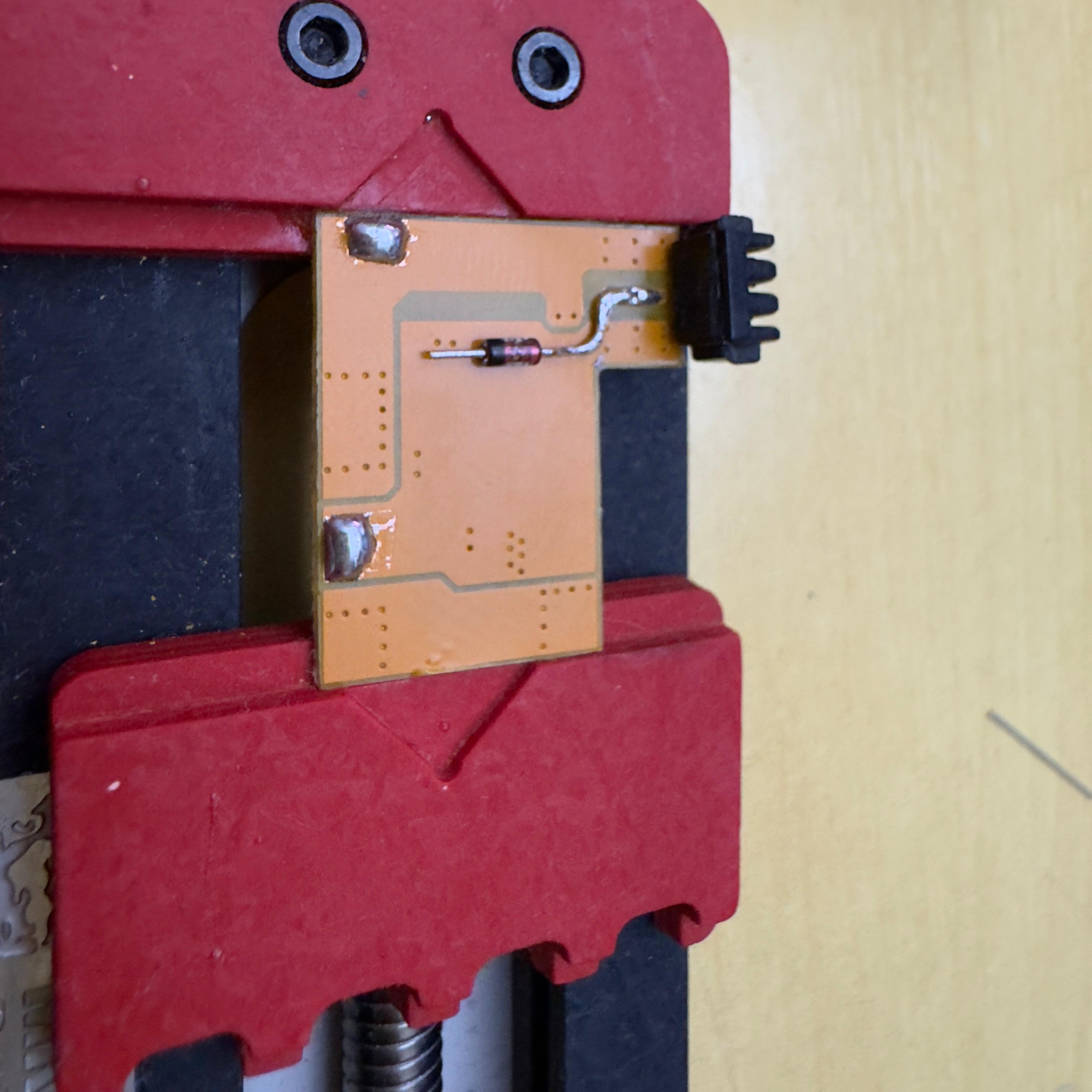
Polarity matters. The cathode faces the battery PCB; flip it and nothing will talk.
Wire the data pair
Solder a twisted pair onto the two contiguous data pads on the battery PCB — these end up at the FT232RL’s RX and the post-diode TX node respectively. Twist the wires. It’s not cosmetic: keeping the two conductors tightly coupled cancels the EMI they’d otherwise pick up, so the serial frames the PSP exchanges with the FT232RL make it across cleanly. Run the pair flat or loose and you risk garbled data — exactly the kind of intermittent, hard-to-debug failure that has you blaming your soldering when the wiring is what’s wrong.
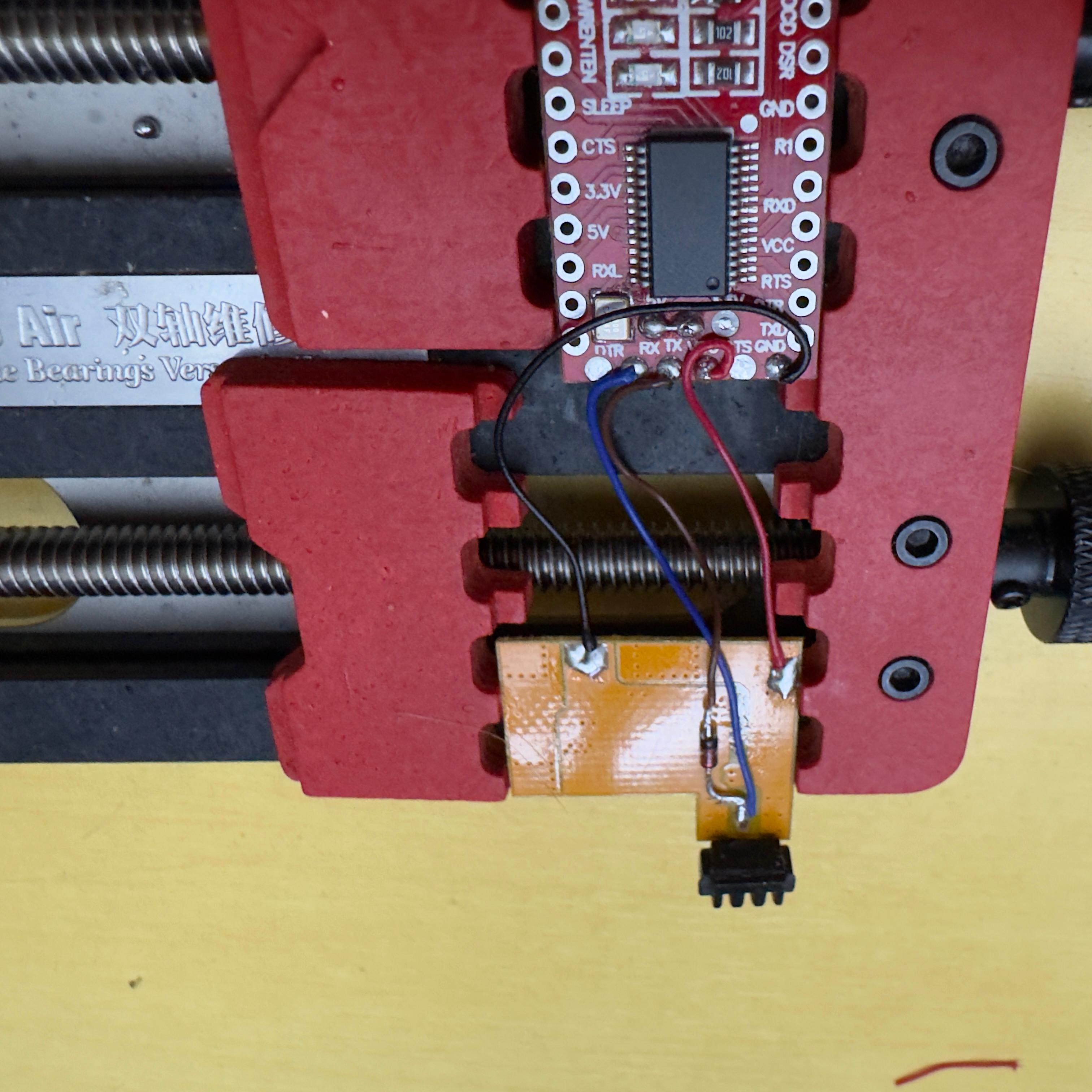
Wire VIN, GND, and signal to the FT232RL
Run wires from the battery-side PCB to the FT232RL’s pin row. Keep them short — every extra millimetre is one more chance to short something against the case.
- 5V (VIN) → red, to the 5V pin
- GND → black, to the GND pin
- TX → out of the FT232RL’s TX, onto the free leg of the diode
- RX → directly to the central data pad on the battery PCB
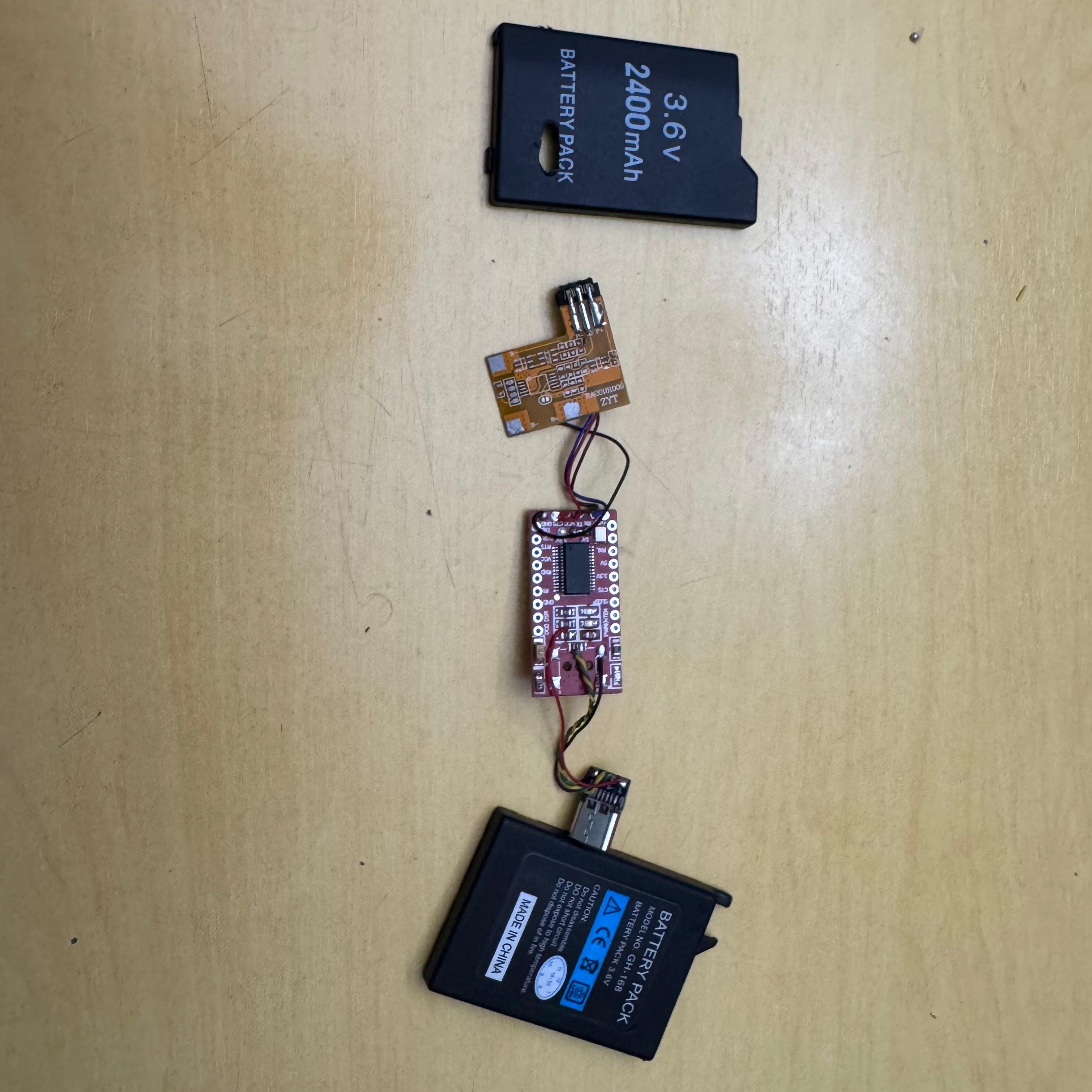
The wider view below shows the same FT232RL once TX is sitting on the diode and RX is bypassing it:
Carve the case
The original case has no opening for USB-C. Mark and dremel a slot until the new port slides flush. A drop of hot glue holds it during test fitting; switch to permanent adhesive once you’re sure the port lines up with the FT232RL inside.
While the case is open, drop the original PSP-side connector back into its slot — the gold-pin block at the bottom of the shell. The boards stack on top of it.
Final layout
Lay everything out in the order it’ll go in: protection PCB at one end, FT232RL in the middle, USB-C connector and donor-cell space at the other end. Wires loop between them.
Stack and close
Fold the boards into the case in that same order. The FT232RL goes on top of the protection PCB, separated by a strip of electrical tape so nothing shorts. Route the wires so the case still closes flat.
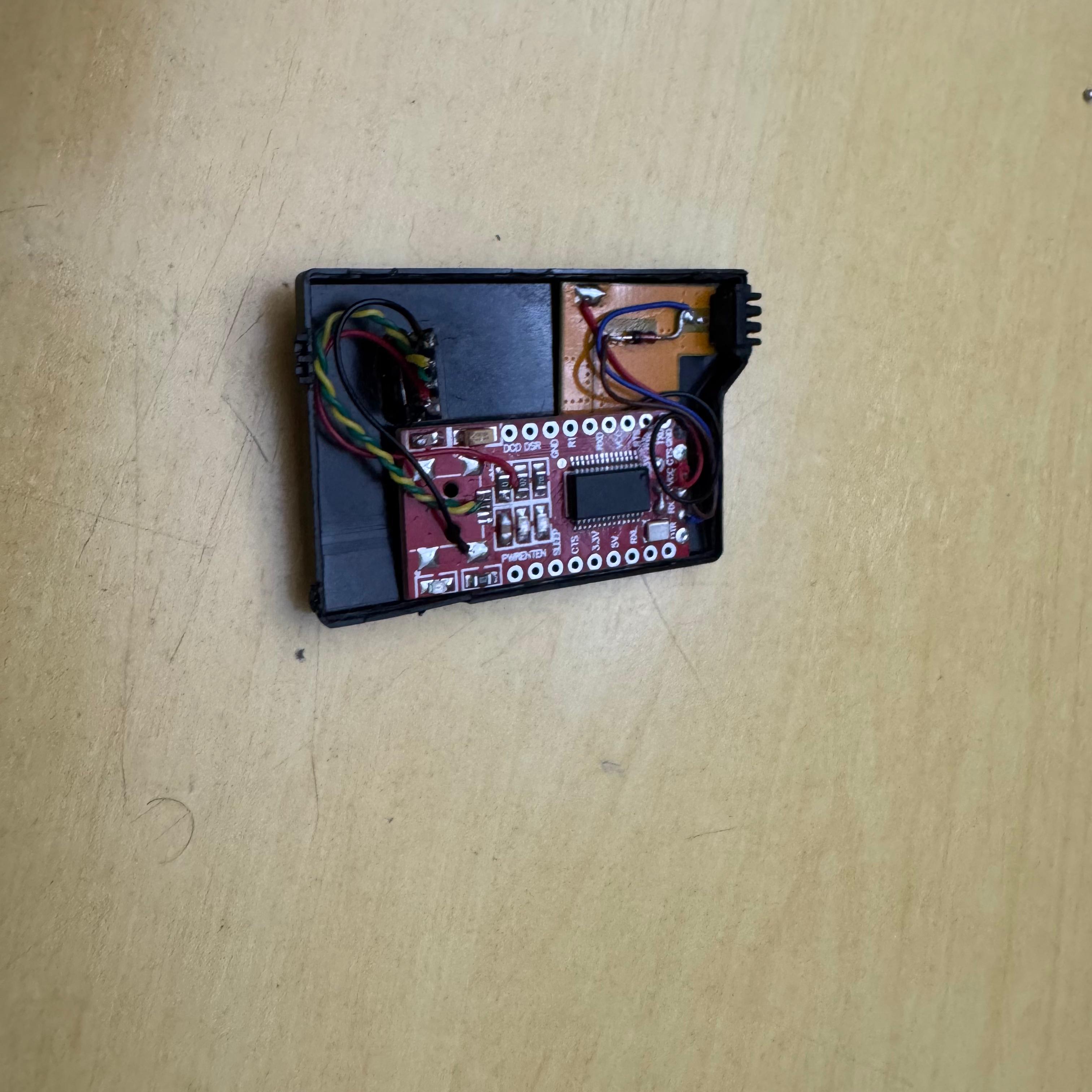
Snap the halves together and seal with a strip of electrical tape around the seam. Plug USB-C in, watch the PSP — and do not skip a quick continuity check before the first power-on.
Done
Second time around the build takes about an hour and a half end to end. The first attempt took me closer to four because I trashed the first protection PCB scraping too aggressively. If yours doesn’t work first try, check the diode orientation before anything else; that’s the failure mode I see most often when people ask.
Special thanks to Zecoxao for the original research that makes this mod possible.